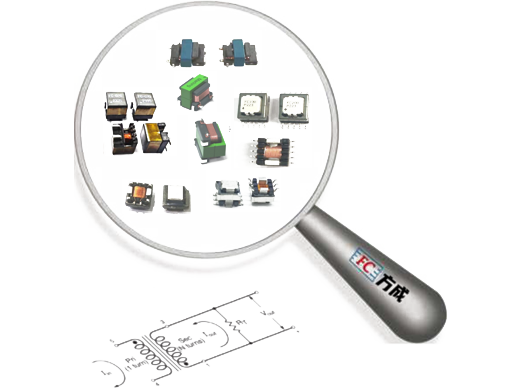
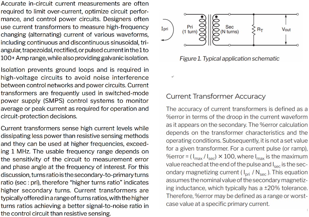
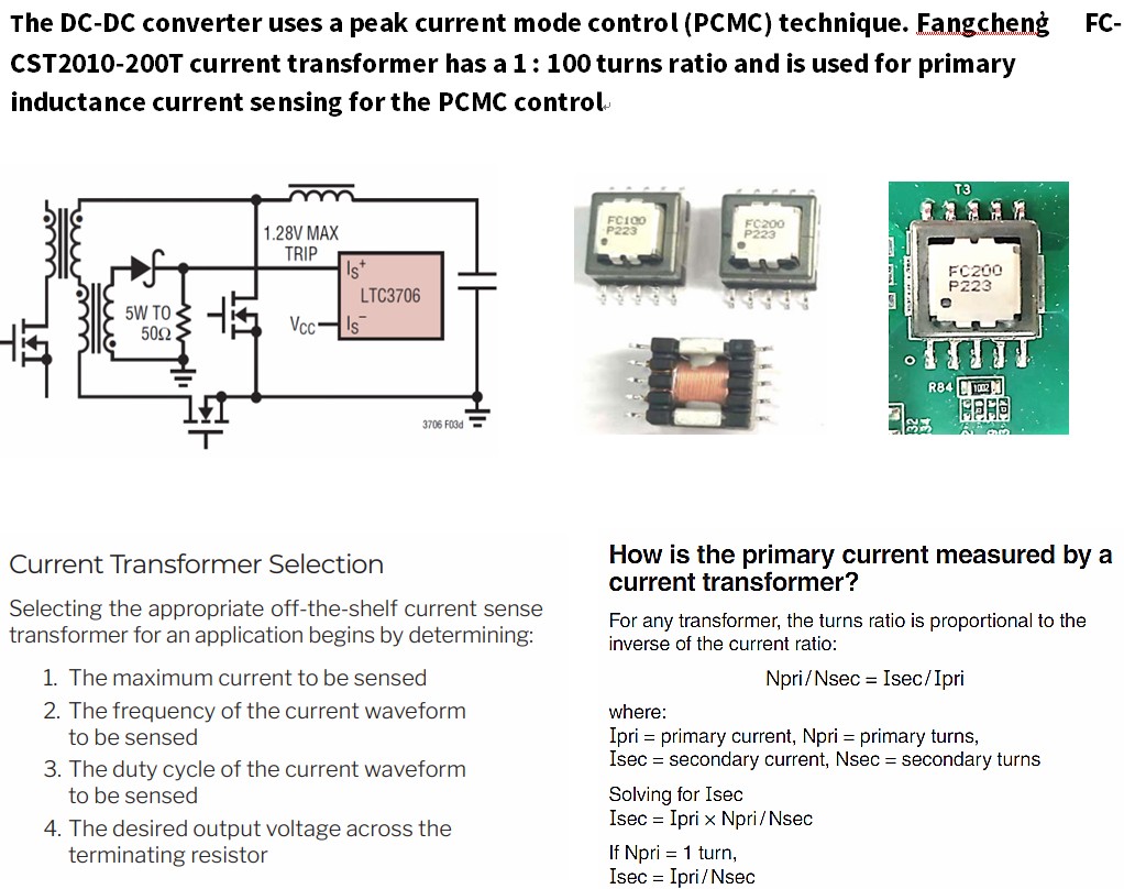
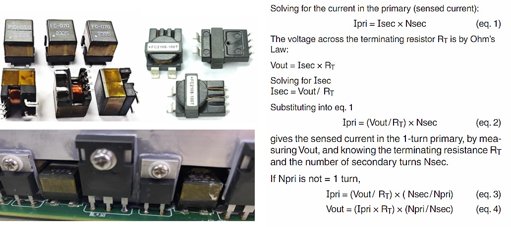
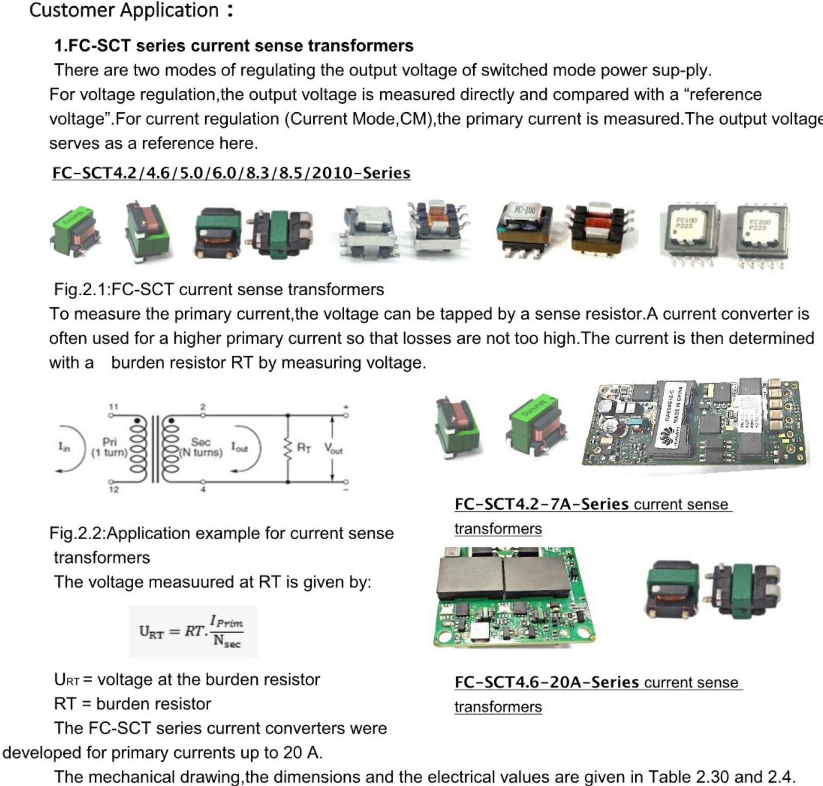
- Current-sense transformers create an alternating current in the secondary winding that Is proportional to the current passing through the pnmary winding. The current in the secondary is converted by a burden’ resistor - or terminating resistor (RT) - to a low voltage that can easily be measured in circuit.
- A typical off-the-shelf current sense transformer has a 1-turn primary and a high-turns secondary. Alternating current passing through the primary winding creates a magnetic field that Is coupled to the secondary. This field develops a voltage across the secondary and RT. With a 1-turn primary, the voltage drop (V) across R1 is proportional to the current through the primary (1.) according to this equation: V= (l X RT)/ N. where N is the number of secondary winding turns. Therefore, selection of the terminating resistance is important In setting the correct maximum output voltage corresponding to the maximum expected primary current.
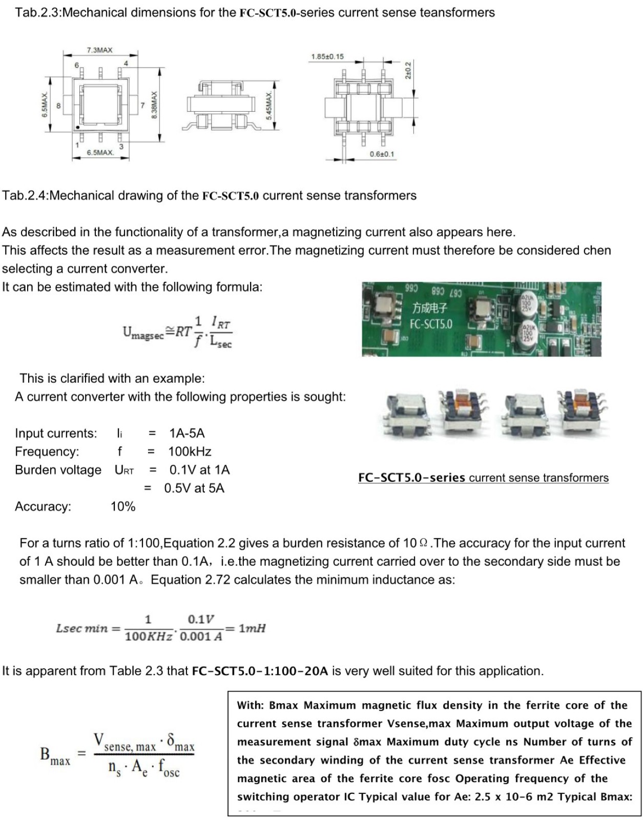
| Part Number | Turns Ration | Current Rating2 NP,(A) | Secondary Inductance (mH MIN) | DCR (mΩ MAX) | Hipot(VRMS) | |
| Primary(8-7) | Secondary(1-3) | Np-Ns | ||||
| FC-SCT5.0-1:20 | 1:20 | 20 | 0.08 | 0.75 | 550 | 1500V |
| FC-SCT5.0-1:30 | 1:30 | 20 | 0.18 | 0.75 | 870 | 1500V |
| FC-SCT5.0-1:40 | 1:40 | 20 | 0.32 | 0.75 | 1140 | 1500V |
| FC-SCT5.0-1:50 | 1:50 | 20 | 0.5 | 0.75 | 1500 | 1500V |
| FC-SCT5.0-1:60 | 1:60 | 20 | 0.72 | 0.75 | 2250 | 1500V |
| FC-SCT5.0-1:70 | 1:70 | 20 | 0.98 | 0.75 | 4750 | 1500V |
| FC-SCT5.0-1:100 | 1:100 | 20 | 2.0 | 0.75 | 5500 | 1500V |
| FC-SCT5.0-1:125 | 1:125 | 20 | 3.0 | 0.75 | 6500 | 1500V |


